The AEM EMS is very unusual compared to other engine management systems when it comes to transmitting MAP (ie. boost) pressure over telemetry. Most systems transmit MAP as a unit like PSI or KPA. The AEM EMS transmits MAP as “Engine Load” where the range of the MAP sensor is scaled over 0-100%. This adds an extra step when setting up telemetry products like the gaugeART Video Gauge Adapter.
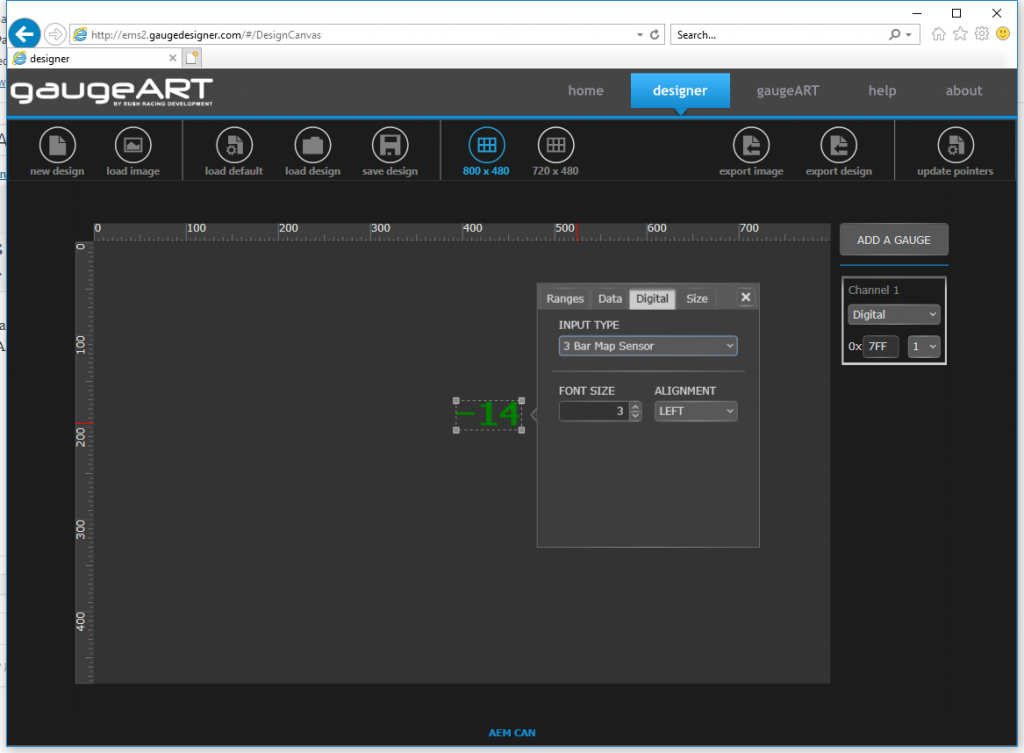
For digital gauges:
- Set gauge to “Digital”.
- Set Input Type to the MAP sensor that you are using.
- The gauge will automatically reflect the output from the EMS (within .1-.2 PSI).
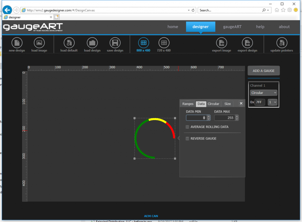
For circular or bar gauges:
- Circular or bar gauges are more complex because the gauge has to match the range of “Engine Load” you wish to display. For example: if your engine has a 4 BAR MAP sensor, the full range of the gauge (0-100%) would be 1 BAR in vacuum and 3 BARs in pressure or -14.6 – 0 PSI and 0-43.5 PSI. This is transmitted as 0-255 bytes from the ECU where 0 = 0% engine load and 255 = 100%. If your gauge is -14.6 – 0 – 43.5 PSI, this would mean that you’re seeing the full range of the data from 0-255 and the gauge should be configured as shown below.
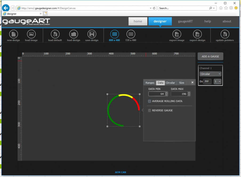
- Due to the unusual way AEM does MAP pressure, things are more complex when you only want to see a portion of the range of the “Engine Load”. For example, if you’re using a 4 BAR MAP sensor, and you want to display only positive pressure (0-30 PSI for example) you would be displaying only about the middle of the range of the sensor from 0 – 30 PSI instead of -14.5 PSI to 43.5 PSI.
- To calculate what byte range is required, first, calculate the byte scale (full range of the sensor over 256 bytes).
byte scale = (full range of sensor / 256 bytes)
byte scale = 58 PSI / 256 = .227 - Next, calculate your minimum byte (where you want the gauge to start) as
minimum byte = (minimum display value – minimum sensor value)/byte scale
minimum byte = (0-(-)14.5)/.227
minimum byte = 14.5/.227
minimum byte = 64 - Next, calculate your maximum byte (where you want the gauge to start) as
maximum byte = (maximum display value – minimum sensor value)/byte scale
maximum byte = (30-(-)14.5)/.227
maximum byte = 44.5/.227
maximum byte = 196 - Use the minimum and maximum byte in the window as shown. Now, your displayed range of the sensor will match the sensor value.