Take these steps to configure your Link & Vi-PEC (G4+, G4X, & G5) ECUs for use with the gaugeART Chroma Gauge.
For normal channels:
- Open tuning software and load a calibration or connect to ECU.
- Select ECU Controls tab.
- Select CAN Setup option. The CAN Setup screen is shown below.

- CAN Module: select the CAN module that the CAN Gauge is wired to (some ECUs have only 1, some have 2).
- Mode: “User Defined”.
- Bit rate: the default bit rate is 1 Mbit/s. If the bit rate will be changed, make sure to change the bit rate in both the Link software and in the gauge’s web app (under CAN Settings).
- Data: click an available data channel (Channel 1 selected in the example above).
- Mode: while that channel is selected, select “Transmit Generic Dash” from drop-down as shown.
- Transmit: “20Hz” as shown.
- ID: “56” as shown.
- Format: “Normal” as shown.
- Click OK.
For extended channels (available for CAN Gauge only):
- Data: click an available channel under Data (Channel 2 selected in the example below).
- Mode: “Link CAN Gauge Extra”
- Transmit: “20Hz” as shown.
- ID: “49” as shown.
- Format: “Normal” as shown.
- Click OK.

For CAN Keypad (gaugeART Chroma only):
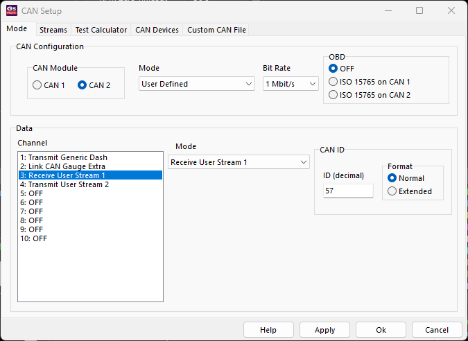
For the optional keypad functions to work, the Link ECU must be setup to receive and transmit CAN messages.
- Select the CAN module that the gauge is connected to.
- Select an available channel and select “Receive User Stream 1” from the Mode drop-down.
- ID = 57 (normal format).
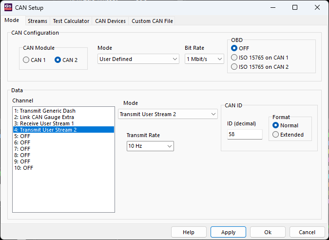
- Select an available channel and select “Transmit User Stream 2” from the Mode drop-down.
- ID = 58 (normal format).
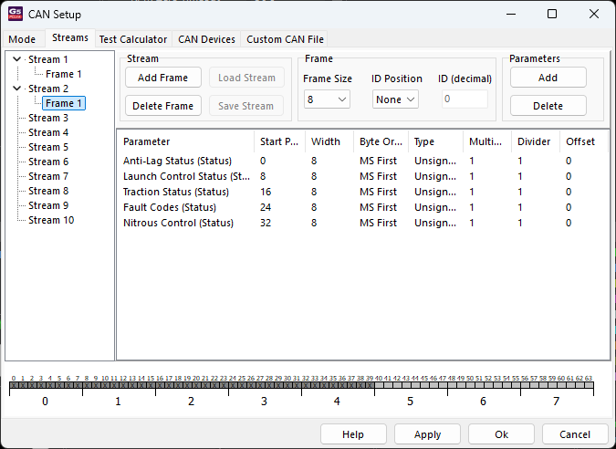
- Click the Streams tab. Under Stream 1, click Add Frame.
- Populate the list exactly as shown below for Frame 1 – making sure the parameters and Start Positions match the list below. The functions (like Anti-Lag) will be shown after the functions have been assigned to the CAN inputs.
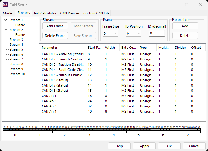
- Repeat the same process for Stream 2, and populate the list exactly as shown below – making sure the parameters and Start Positions match the list below.
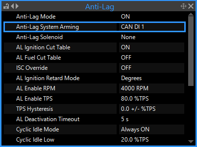
- You must select the correct CAN DI for the correct function to display. For example, Anti-Lag must use CAN DI 1, as shown below.
- For Analog inputs, the gauge transmits 0-255. This may be used as a trim axis for a function like Boost Target.