
- Switches: The gaugeART Panel Mount CAN Gauge includes a wire harness for switches. Switches are only required if you will have more than one page of gauges. The switch wires are pre-terminated in to the 6 position connector. Any momentary switch may be used.
- LED: The LED output is triggered when a gauge warning is triggered. The LED output is optional. The display will also display a warning screen when a warning is triggered. An LED is supplied with terminals pre-installed to the wires. The terminals will be passed through the mounting hole, then terminated in to the 6 position connector. If a different LED is used, an LED designed for 3.3V is required. Damage to the gauge from an improper LED is not covered under the warranty. The optional LED requires a 4mm hole to be drilled. Once installed, insert the terminals in to the 6 position connector according to the diagram below.
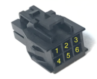
| 1 – Switch Next (green)
2 – Switch Previous (blue) 3 – LED+ (3.3V) (red) 4 – Switch Common (black) 5 – Switch Common (black) 6 – LED Ground (black) |
 |