 Due to the complex nature of AEM’s configurable serial telemetry output, the following instructions are made available for advanced users of gaugeART Serial Video Gauge Adapters.
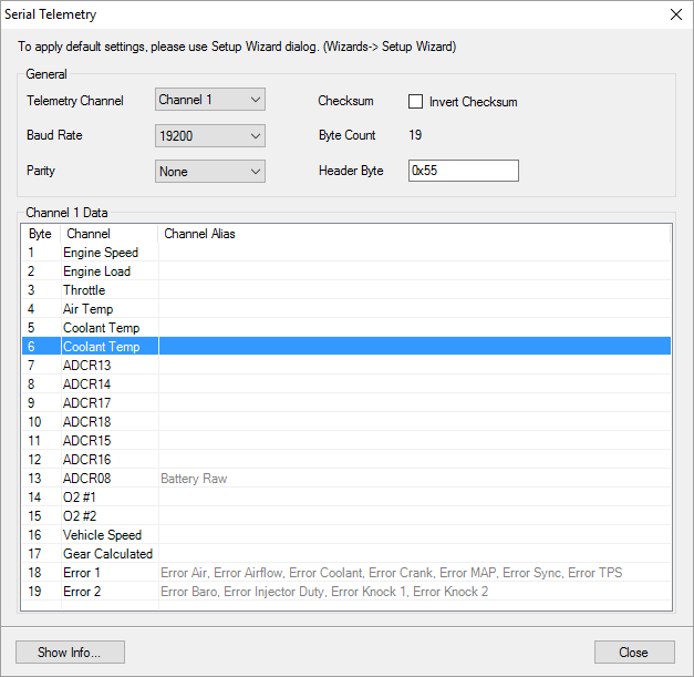
Default gaugeART Video Gauge designs use AEM’s telemetry output for the AEM Serial Datastream Gauge which consists of 19 pre-configured channels (as shown to the right).
Your design’s gauges must use the same channel configuration as the telemetry your ECU is outputting. For example, if your design has a coolant temperature gauge, and you are using the telemetry shown to the right, your coolant temperature gauge must be number five in the channel list of your design as coolant temperature data is being sent out on the fifth channel of the telemetry output. If your design has a coolant gauge as the sixth channel, you can either change the design and move the gauge to channel five, or change your ECU telemetry to make the sixth channel “Coolant Temp”.
In these instructions, we will cover customizing the telemetry output from the ECU.
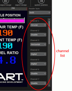
- You should first determine what channels your design uses. There are two ways to do this: 1) if you are using one of gaugeART’s designs, go to the specific design you are working with in Design Gallery, and view the design’s telemetry list 2) open the design’s .GAD file in gaugeDesigner (click here for instructions on how to open designs in gaugeDesigner). The image below shows the channel list in gaugeDesigner. Click the channel name (ie. Channel 1) to highlight the gauge that channel corresponds to.

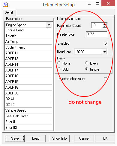
- To customize the telemetry output, open the ECU’s software (Series 1: AEMPro or Series 2: AEMTuner) and open the telemetry setup window with your laptop connected to the ECU.
Series 1 AEMPro: Setup > Advanced Setup > Telemetry > Telemetry Setup
Series 2 AEMTuner: Tools > Configure Telemetry > Serial Telemetry - Leave the parameter count, header byte, baud rate, Parity, and Inverted checksum unmodified.
Click the channel you wish to modify, and change it to the data you wish to display then hit the enter key. In the example image below, the sixth channel is changed to coolant temp (Series 2 AEMTuner shown – the process is the same for Series 1 AEMPro) . If you will be making advanced gauge designs, it is good to have an understanding of how the serial telemetry data stream works. To view advanced telemetry:
- Open Telemetry Setup:
Series 1 AEMPro: Setup > Advanced Setup > Telemetry > Telemetry Setup
Series 2 AEMTuner: Tools > Configure Telemetry > Serial Telemetry - Click “Show Info” on the serial telemetry setup window to show the current serial telemetry configuration. The table below shows the telemetry configuration used by gaugeART’s default gauge design.

Key:
- Byte: Also known as data channel. There are nineteen data channels in the serial data stream. The numbered byte channel corresponds to the same numbered channel that gaugeART uses (eg. in gaugeDesigner, if “channel 1” is used for a gauge, it will read the engine speed).
- Name: Indicates which data parameter is being streamed in that data channel.
- Units: Units that the data channel is streamed in.
- Min, Max, and Scalar: There are 256 bytes or “data buckets” that make up each data channel. The minimum and maximum values are spread over these 0-255 buckets where Min = 0 data bucket and Max = 255 data buckets. The separation of each bucket is the scalar. Example: if you view byte or channel 1, for engine speed, you will find that the minimum is 0 and the maximum is 25,600 (rounded to the ones decimal position). Each bucket is separated by 100. So, data bucket 0 = 0, 1 = 100, 2 = 200, 3 = 300, and so forth until 0 = 25,600.
