The AEM EMS Series 2 ECUs do not have a dedicated CAN connector. Instead, they require you to terminate the wires to certain terminal positions. See the instructions included with your AEM EMS for the pin-out specific to your application. 2000-05 Honda S2000 is provided as an example.
2000-05 Honda S2000 (AEM EMS Series 2 part no. 30-6052)
There are four wire connections that will be made:
| gaugeART wire color | ECU terminal (30-6052) | function |
| black | D1 | ground |
| red | D4 | +12V |
| white | D10 | CAN high |
| green | D14 | CAN low |
Note that many of the AEM EMS Series 2 have available HS outputs (+12V ignition power) and LS or spare injector outputs (ground). These can be used to power the gaugeART device. For applications other than 2000-05 S2000, if a HS (+12V) or LS (ground) is not available, they can be wired to a fused ignition power source and chassis ground.
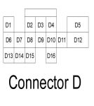
Identify the terminal positions (note, the diagram is from the wire side of the connector. Note that this connector and terminals are included in the AEM 30-6052 box. Other applications may differ.
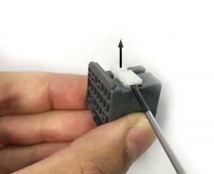
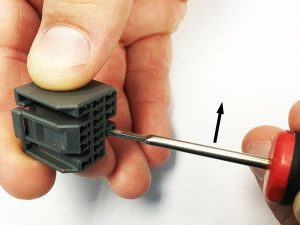
Strip and crimp the wire to the terminals (see instructions included with gaugeART product). To open the terminal retainer, lift up as shown.
Insert the terminal with the tabs on top as shown.
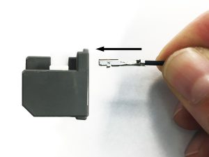
Once all four are inserted, press down on the white retainer to lock, and insert connector into EMS. If the terminal ever needs to be removed, lift up on the terminal lock and pry out as shown.
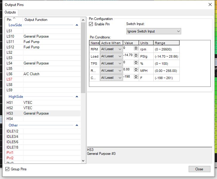
If you used a HS, LS, or unused injector output to power the gauge – these need to be configured to be turned on. Connect to the AEM EMS and go to Tools > configure outputs. Select the output you are using, and configure the output to be on whenever ignition is on, like in the example below. Once this is done – make sure that you have enabled CAN telemetry in the software.